
Difficult even with the physical object? Reverse Engineering of Gears
Introduction

Gears are a common example of a gear that we receive requests for reverse engineering due to their failure. Although the basic mechanism of transmitting force is the same, the shape and combination of gears can vary greatly depending on their application.
Every time I research gears, I make new discoveries and am amazed by their profound complexity.
Many older machines rely on numerous gears for power transmission, and damage or deterioration of these gears can cause deformation, leading to the machine becoming inoperable or experiencing a decline in performance.
Even if we receive a request for reverse engineering on such a machine and determine that the gears are the cause of the problem, there are numerous challenges in creating an identical gear.
In this column, we'll explain the surprisingly difficult process of measuring gears!
1. What is the invisible reference circle, even though it's a standard?
Gears have a reference circle, or "reference circle," that serves as the basis for how they mesh with other gears. The distance at which these reference circles touch determines the relative positions of the gears, making it a very important element.
However, the reference circle is not drawn anywhere on the gear, and there is no way to directly measure the reference circle by measuring anywhere on the actual object.
So how do you determine the base yen?
Tooth size (module) × Number of teeth (tooths)
It can be calculated as follows.
What makes things even more complicated here is the existence of modules, which are the sizes of teeth.
2. How do you measure it? What is a module?
The module is a coefficient that represents the size of the teeth. The larger the module number, the deeper and wider the teeth of the gear will be.
The module is not documented anywhere and must be measured and calculated. The calculation formula is as follows:
Height from the base of the tooth to the tip of the blade ÷ 2.25
Thinking that the calculation would be complete once the measurement was taken, and attempting to measure with calipers, one encounters a certain problem depending on the gear.
This means that when the number of teeth is odd, the height from the tooth root to the cutting edge cannot be measured using calipers.
If the number of teeth is even, the opposite side of the tooth root is also a tooth root, so the tooth height can be calculated by measuring the width between the tooth roots and the cutting edges with calipers. However, the difficulty of measurement increases dramatically when the number of teeth becomes odd.
3. Even more difficult!? Other gears
Everything discussed so far has been about spur gears, where the teeth extend parallel to the axial direction.
Some gears are helical gears, which have teeth angled relative to the shaft, and bevel gears, which are conical in shape.
These gears are even more difficult to measure, and accurate measurement is impossible without using specialized measuring instruments.
Please contact us if you need assistance with drawing machines or machine parts!
Our company has experience measuring gears of various shapes, not just spur gears. We also offer consultations regarding machinery, including repairs to old, malfunctioning machines.
If you have any problems with your old machine, please feel free to contact us using the inquiry form below!

Enhanced safety features through reverse engineering: Area sensors
Introduction Reverse engineering often involves requests to recreate parts from older machinery that are no longer supported. However, many older machines prioritize production capacity and do not meet modern safety standards, and the machines are problematic…
Enhanced safety features through reverse engineering – Double switch
Introduction Reverse engineering often involves requests to recreate parts from older machinery that are no longer supported. However, many older machines prioritize production capacity and do not meet modern safety standards, and the machines are problematic…

Reverse Engineering for Enhanced Safety – Safety Fences
Introduction Reverse engineering often involves requests to recreate parts from older machinery that are no longer supported. However, many older machines prioritize production capacity and do not meet modern safety standards, and the machines are problematic…

Reverse Engineering and Components ~Screw Shafts~
Introduction When older machinery is beyond repair, we receive inquiries about reverse engineering. While we receive inquiries about a wide variety of machines, there are certain parts that we are surprisingly often asked to work on. This column will discuss such parts…

Reverse Engineering: How to Avoid Failure? Part 2
Introduction: Reverse engineering is a technique that can repair parts of machines whose support has ended, but it cannot repair all products and parts, and there is a possibility of failure. This column will explain how to perform reverse engineering…

Points to note when choosing grease
Introduction: Most machines with rotating parts, such as shafts, use bearings. Inside the bearings, grease is sealed to prevent wear and ensure smooth operation. Different types of grease are used depending on the application…

Reverse Engineering Techniques: Material Selection Based on Application (Part 3)
Introduction When using reverse engineering to repair old machines and restore parts, the material of the part can be a headache. If you make a new part using the same material as the damaged part, you can't easily distinguish it by measuring it with measuring tools or by looking at its color because the original part is still available...

What are the advantages of 3D printers that shine through reverse engineering?
Introduction 3D printers have become commonplace, not only in the manufacturing industry but also among many people who use them personally as a hobby. However, there are many advantages to effectively utilizing 3D printers in the field of reverse engineering. This time…

What are the essential points to check when reverse engineering!? <Part 3 - Components>
Introduction Reverse engineering, while a broad term, deals with a wide variety of machines and parts. Analyzing such diverse objects using reverse engineering is no easy task. In fact, when proceeding with reverse engineering…

Reverse Engineering Techniques: Material Selection Based on Application (Part 2)
Introduction When using reverse engineering to repair old machines and restore parts, the material of the part can be a headache. If you make a new part using the same material as the damaged part, you can't easily distinguish it by measuring it with measuring tools or by looking at its color because the original part is still available...
Reverse Engineering Techniques - Selecting Materials by Use, Part 1
Introduction When using reverse engineering to repair old machines and restore parts, the material of the part can be a headache. If you make a new part using the same material as the damaged part, you can't easily distinguish it by measuring it with measuring tools or by looking at its color because the original part is still available...
Reverse Engineering Techniques - Material and Substance Investigation Part 2
Introduction When using reverse engineering to repair old machines and restore parts, the material of the part can be a headache. If you make a new part using the same material as the damaged part, you can't easily distinguish it by measuring it with measuring tools or by looking at its color because the original part is still available...

Reverse engineering technology - material and substance investigation
Introduction When using reverse engineering to repair old machines and restore parts, the material of the part can be a headache. If you make a new part using the same material as the damaged part, you can't easily distinguish it by measuring it with measuring tools or by looking at its color because the original part is still available...
How to avoid failure in reverse engineering? Part 1
Introduction Reverse engineering is a technique that can restore parts of machines that are no longer supported, but it cannot restore all products or parts, and there is a possibility that it will fail. In this column, we will explain how to reverse engineer...
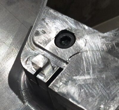
Examples of reverse machining of molds made by other companies
Introduction When you have trouble with an old machine, the most common problem is repairing broken parts. If there are drawings for the parts, you can recreate them based on those, but with old molds, there are often no drawings, so repairs are often abandoned...